36 Paradise Building, Room No-3, Madhu Vihar, Patparganj DELHI- 110092

Tensile Membrane Structure
As manufacturers, suppliers or clients we shape the future of Tensile structures on a daily basis. As diverse membrane structures are constructed and new fabrics developed, there is an increasing confidence in the structural capacity and longevity of architectural fabrics as building materials. Amazing and inspiringly beautiful buildings are built year by year. World class sporting stadiums, Olympic games venues, entire airports and railway stations, huge shopping malls, in locations never before imagined – in deserts or on snow, on rooftops 50 storeys high, in the wet tropics. So it is with such benchmarks we drive the growth and adaptability of Tensile structures to so many areas of daily life. Steel frameworks and quality stainless steel fittings such as turnbuckles and shackles enhance the aesthetics of these structures. Tensile structures are available in various fabric types ranging from high performance teflon-coated fibreglass to more price conscious laminated materials and meshes.
Tensile Architect provides a full spectrum of services from design development, engineering expertise, construction documents, manufacturing and installation. We have gathered a team of designers, steel fabricators, painters, engineers, fabricators and project co-ordinators that can take the project from idea to completion stage within the one company. We are committed to achieving our client’s objectives in a Tensile structure whether it be uniqueness, high visibility, enhancing corporate identity, functionality, to allow patrons to sit in comfort or to screen or protect. Flexibility of design, advanced materials and streamlined processes allow Tensile Architect to offer a complete approach.
Key steps in Tensile fabric structure design
- Determining parameters and objectives of the structure
- Shapes and Forms
- Components of a structure
- Engineering
The design development phase of a Tensile membrane structure project usually revolves around a collaborative effort often involving client, architect, engineer, head contractors and fabricator. The first step is to determine the boundaries of the Tensileed structure. Boundaries include walls, beams, trees, fences, columns and cables heights, sub strata services and composition. What does the structure need to achieve eg high visibility, weather protection, shade at certain times of the year, screening?
The fabric is either continuously fixed to walls or beams or attached to columns. In most cases the fabric forms a curved edge or ”a catenary curve“ between connection points requiring a cable or webbing to carry loads to the major structural points. Catenaries are usually curved inward from 7 to 15% of the total length of the span. Once the parameters have been determined, the next step is to develop a design. This could involve either a basic design or computer aided design.
Designing shade for the home
In the case of small projects where a design is straightforward, a sketch can be prepared, with measurements, parameters, fabric selection and costs determined quite expediently. Regardless of the size of the project there are stringent design, fabrication and installation guidelines to be followed. It is often with smaller structures where the client is looking to the installer for direction and expertise that compliance, quality training and skill are particularly important. Design factors to consider on domestic work are site access, weather protection needed, council requirements, options and availability of materials, impact of underground services on the location of structure and explanation of the design to the client. While not all Abacus Shade Structure projects are complex all projects are engineered, carry warranties, are performed by trained personnel and adhere to statutory requirements.
Computer Aided Design
Increasingly, Tensileed membrane structures are created using sophisticated computer technology. Computer software not only helps create a 3D model, which can be viewed from different angles, it can be customised to provide information to facilitate fabrication and installation. It can determine the amount of fabric to be used, how it should be cut, dimension of each piece, the size and length of structural members, the size and length of cables required. The designer is also able to modify the shape. The increasing complexity of Tensile membrane structures has made design software and computer cutting and plotting machines indispensable to the tensile structure designer. An understanding of different shapes and form is essential to the design of Tensile fabric membrane structures. Steel frame configuration and the curvature of the fabric spanning between the frame determines the basic form.
The Most common forms of Tensile membrane structures include:
- Mast supported system
- Point or frame supported system
- Repeat patterned system
- Cantilevered arch supported system
- Simple saddle hypar system
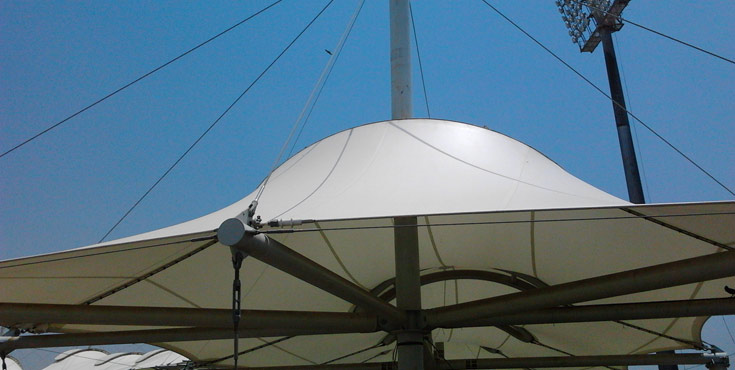
Mast-supported systems, similar to tent-like structures in form, are made of one or several peaks supported by central poles. A compression ring or “bale” ring connects the fabric to the central support of the mast and facilitates erection and stressing of the fabric. Circus tents, Umbrellas and Inverted Umbrellas fit into this category. Point-supported systems produce a clear span with no central mast. An exterior frame or a series of peripheral masts supports the fabric peaks. This is a popular design system where an irregular space exists or a free form structure is sought.
The Parallel Edge or Repeat Pattern System is another approach to creating a clear span structure. The fabric is supported along the perimeter by parallel masts with the fabric alternating between high and low points. Cantilevered arch-supported systems also avoid interior supports in addition to introducing curved compression members as the main supporting element. For lateral stability in cantilevered arch-supported systems, cross arches or diagonal bracing may be used.
To avoid interior supports as well as massive footings, a Span Shade Frame supported system may be appropriate. Fabric is attached to a structural frame. The primary structural components carry the majority of forces within the system, so that the fabric is used purely as a cladding. The Tensile Architect Shade structure and knuckle system has made frame supported systems modular and straightforward for installers. Finally, the simple saddle system or hypar is a four or more point structure formed when the fabric is stretched tautly between a set of alternating high and low points. Much of the appeal of hypars is in their changing 3D appearance from any viewing angle.
Membrane Fabric
The membrane forms the enclosure or skin of the structure and can be fabricated a number of ways. It can be sewn, glued, electronically welded and/or heat-sealed. There are a number of seam styles, overlaps and reinforcements that differ from project to project. The most common form of fabrication used is high frequency overlap welding. The different material properties i.e. strength, thickness, elasticity, weight, etc., make material selection critical. A need for the membrane to be highly abrasion-resistant, low maintenance and “vandal proof” also influences the choice of suitable materials.
Specialised Hardware
Tensile Structure hardware consists mostly of parts made for yacht racing, bridge building and rigging. Shackles, turnbuckles, terminal end swages, wire rope grips, are just a few of the hardware choices available. Tensileed structures commonly consist of steel cabled hems with threaded end fittings. Hardware comes in 316 and 304 grade stainless steel, galvanized and custom finishes. Tensileed Structure details have changed over the past 30 years from heavy bridge building components to state of the art yacht racing technology as slick, shiny stainless steel replaced heavy industrial looking materials. Although the “less is more” approach is the most desirable, the structural loads and requirements needed for a Tensileed membrane structure dictate the size and shape of most details.
Aluminium Tracks
Tracks are normally used to provide a watertight seal along a gutter, beam or adjacent building. The material most often used is painted or unpainted aluminium. The track is extruded into a distinct profile and grading.
Posts and Framework
At the core of a Tensileed membrane structure is the support frame. This is generally the heaviest and often, the most costly component of the structure. A significant amount of the steelwork may hidden in deep concrete footings. The amount of steel used is dependant upon loads imposed, the design and the membrane used and must factored into the engineering for the project.
Other Production Considerations
Various production processes eg welding, forging, casting, etc. have their own advantages and disadvantages that dictate the design of structural components in a membrane structure. Transport and Site Access: The ability to transport components to the job site and then unload and position components into place must be considered. Load Conditions: Testing for water run off needs to be considered. Membrane Structures need to be pitched. The collection of water on flat fabric areas, known as “ponding”, must be avoided. A shade structure should have a minimum 1.25:1 fall ratio.
Engineering documents include the design and detailing of structural components; the selection and specification of fabric material; a detail and schedule of cables and hardware; and cutting patterns for fabrication. Concept drawings are engineered, and structural calculations are based on these. Upon approval, shop drawings are produced for steelwork and footings and finally fabric patterning completed. Final fabric selection is derived from analysis of the loads and stresses placed on the structure. Fabrics vary in weight, tear strength and shade protection offered. The Engineer may monitor installation during construction and certify the structure and upon completion.